

Inconel 718 is a precipitation-hardened nickel-chromium superalloy that derives its strength from γ′ (Ni₃Al, Ti) and γ′′ (Ni₃Nb) precipitates. It maintains excellent mechanical properties and corrosion resistance at elevated temperatures, making it a go-to material for aerospace engines, gas turbines, nuclear reactors, and offshore engineering.
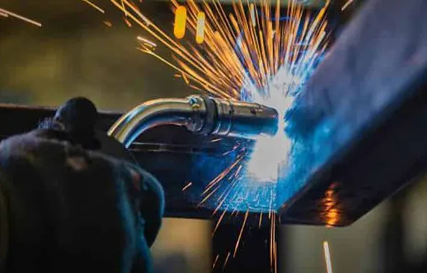
However, these strengthening mechanisms also make Inconel 718 challenging to weld. TIG welding, also known as GTAW (Gas Tungsten Arc Welding), is widely used for joining Inconel 718 because it provides precise heat input control, excellent arc stability, and clean weld quality.
This comprehensive guide covers everything you need to know about TIG welding Inconel 718, including welding parameters, filler metal selection, step-by-step welding techniques, common defects, and defect prevention.
Although Inconel 718 is considered one of the more weldable precipitation-hardened nickel alloys, it is still susceptible to several metallurgical defects during welding.
Hot cracking is one of the most important defects to control when TIG welding Inconel 718. It is associated with niobium (Nb) segregation during solidification and the formation of low-melting constituents, including Laves phase, in the interdendritic regions.
High heat input and excessive weld-pool size can increase segregation and crack sensitivity. Therefore, controlling heat input, travel speed, interpass temperature, and weld-pool size is critical when welding Inconel 718.
Liquation cracking can occur in the heat-affected zone (HAZ) when grain-boundary constituents and low-melting phases partially melt during the welding thermal cycle.
The resulting liquid films can become susceptible to cracking under welding-induced tensile stresses. Controlling heat input and avoiding excessive thermal exposure can help reduce the risk.
During solidification, niobium-rich constituents can segregate into interdendritic regions and form Laves phase.
Excessive or coarse Laves phase can reduce ductility and negatively affect weld performance. For this reason, controlling the welding thermal cycle and solidification conditions is particularly important when TIG welding Inconel 718.
Whenever possible, the welding condition of the Inconel 718 base metal should be established before welding. Solution-treated material is generally preferred because welding aged or heavily precipitation-hardened material can increase susceptibility to HAZ cracking.
For critical applications, the applicable material specification and qualified welding procedure specification (WPS) should be followed rather than relying on a generic heat-treatment cycle.
For conventional TIG welding of Inconel 718:
The exact current should always be adjusted according to the thickness and joint design rather than applying one fixed current to all Inconel 718 welding applications.
Pulsed TIG welding can help control heat input, reduce excessive weld-pool size, and refine the weld microstructure.
| Parameter | Typical Starting Range |
|---|---|
| Peak current | 180–220 A |
| Background current | 60–90 A |
| Pulse frequency | 2–10 Hz |
| Duty cycle | 40–60% |
| Travel speed | 150–250 mm/min |
Note: Actual values should be adjusted according to material thickness, joint configuration, tungsten diameter, welding position, and the qualified welding procedure.
Pulse frequency can influence weld-pool behavior, solidification, and microstructure. In critical applications, welding parameters should be qualified through procedure testing rather than selected solely from general reference values.
Heat input is one of the most important factors affecting Inconel 718 weld quality.
For thin Inconel 718 sheet, relatively low and controlled heat input is generally preferred. Excessive heat input can lead to:
The appropriate heat input depends on material thickness, joint design, welding speed, current, voltage, and efficiency of the welding process.
For multi-pass welding, maintaining a low interpass temperature is important for limiting cumulative thermal exposure.
A commonly used target is to keep the interpass temperature below 93°C (200°F) when required by the welding procedure.
Auxiliary cooling may be used for certain applications, but cooling methods must not introduce moisture, oil, contamination, or other substances into the weld area.
Adequate shielding is essential because nickel alloys can be highly sensitive to atmospheric contamination during welding.
Common tungsten choices for TIG welding Inconel 718 include:
The tungsten diameter should be selected according to the welding current and joint configuration. A properly prepared and maintained tungsten electrode helps maintain arc stability and minimizes the risk of tungsten inclusions.
Choosing the appropriate filler metal is one of the most critical decisions when TIG welding Inconel 718.
| Application | Common Filler Metal | Specification |
| Inconel 718 to Inconel 718 | ERNiFeCr-2 | AWS A5.14 / AMS 5832 |
| Inconel 718 to certain dissimilar alloys | Nickel-alloy fillers selected according to the joint and service requirements | Application dependent |
ERNiFeCr-2 is a commonly specified filler metal for welding Inconel 718. It is designed for applications where the welded joint requires properties compatible with precipitation-hardened nickel alloys.
For dissimilar-metal welding, filler selection should not be based solely on the base-metal name. The combination of base metals, service temperature, corrosion environment, required mechanical properties, joint design, and applicable welding specification should all be considered.
Alternative nickel-alloy fillers, including nickel-chromium-molybdenum grades, may be appropriate for specific dissimilar-metal or corrosion-service applications. The final filler metal should be confirmed against the applicable WPS or engineering specification.
ERNiFeCr-2 is particularly relevant when the welding objective is to join Inconel 718 while maintaining suitable high-temperature mechanical performance and corrosion resistance.
When selecting ERNiFeCr-2 filler wire, consider:
The filler metal should be selected based on the complete welding application rather than simply choosing an “equivalent” alloy by chemical composition.
A controlled welding procedure is essential for minimizing cracking, oxidation, and other defects in Inconel 718.
Prepare the joint according to the qualified welding procedure. Remove burrs, sharp edges, oxides, scale, and other surface contaminants.
For thin sections, joint fit-up should be carefully controlled to avoid excessive gaps and unnecessary weld reinforcement.
Thoroughly clean the weld zone and adjacent areas before welding.
Remove:
Acetone or another suitable solvent can be used for final cleaning when compatible with the applicable welding procedure.
Clean gloves and dedicated stainless-steel or nickel-alloy preparation tools should be used to avoid recontamination.
Set the TIG power source to DCEN and establish adequate argon shielding.
Use a suitable gas cup and gas lens when appropriate. For full-penetration joints and thin-wall tubing, establish effective back purging before striking the arc.
Select the tungsten diameter according to the welding current and joint geometry.
Use a properly ground and clean electrode. Avoid touching the tungsten to the workpiece or filler metal during welding.
For Inconel 718-to-Inconel 718 TIG welding, ERNiFeCr-2 is a common filler metal choice.
Select the filler diameter according to the joint thickness, welding current, and required deposition rate.
Maintain a short arc length and avoid excessive arc wandering.
A stable arc helps maintain a controlled weld pool and minimizes unnecessary heat input.
Use the lowest practical heat input that provides complete fusion and the required penetration.
Avoid excessive current, slow travel speed, and unnecessary dwell time. For pulsed TIG, use the pulse parameters specified by the qualified welding procedure.
Keep the weld pool small and controlled.
Add filler metal consistently rather than allowing the base metal to overheat. Avoid excessive weaving because wider weld pools can increase thermal exposure and segregation.
For multi-pass welding, thoroughly remove oxides and surface contamination between passes.
Mechanical cleaning or grinding may be required when oxidation or surface defects are present.
Monitor the interpass temperature and allow the joint to cool when necessary.
Keeping the interpass temperature within the qualified range helps limit cumulative thermal exposure and reduces excessive grain growth.
After welding, inspect the joint according to the applicable quality requirements.
Depending on the application, inspection may include:
Critical aerospace, nuclear, and power-generation components may require more extensive inspection and procedure qualification.
To reduce hot-cracking susceptibility:
Because Nb segregation and Laves phase formation are strongly influenced by solidification conditions, controlling the welding thermal cycle is particularly important.
Oxides and surface contamination can cause weld-quality problems and may contribute to surface defects or inclusions.
Mechanical cleaning between passes is important when visible oxidation or contamination is present.
Use clean, dedicated tools and avoid introducing iron, oil, or other contaminants into the nickel-alloy weld zone.
Pre-weld cleaning is essential for preventing contamination-related defects.
The cleaned weld area should be protected from recontamination before and during welding. Proper surface preparation and handling are particularly important for nickel-alloy TIG welding.
Tungsten inclusions can occur when the tungsten electrode contacts the molten weld pool or becomes contaminated.
To reduce the risk:
Porosity is commonly associated with contamination, inadequate shielding, moisture, or poor gas coverage. Proper surface preparation and shielding are therefore essential.
Pulsed TIG can provide better control over heat input and weld-pool solidification.
The alternating peak and background current can help reduce average heat input while maintaining adequate penetration. When properly optimized and qualified, pulsed TIG can improve weld microstructure and mechanical performance.
Ultrasonic-assisted TIG is an advanced welding technique that introduces ultrasonic vibration into the welding process.
Research has shown that ultrasonic assistance can influence:
Ultrasonic-assisted welding may therefore be considered for research, high-performance, or highly controlled applications where conventional TIG welding presents significant metallurgical challenges.
GTCAW is an advanced variant of GTAW that uses a constricted arc to increase energy density and penetration.
It has demonstrated high joint efficiency in research and specialized applications and may provide an alternative to other high-energy-density welding processes for selected Inconel 718 applications.
However, GTCAW is a specialized process and is not a direct replacement for conventional TIG welding in every production environment.
The appropriate post-weld heat treatment for Inconel 718 depends on the base-metal condition, welding procedure, component design, and applicable material or engineering specification.
For precipitation-hardened Inconel 718, solution treatment followed by controlled aging may be required when the application demands restoration of the specified mechanical properties.
A commonly referenced aging sequence is:
However, the exact heat-treatment cycle should be taken from the applicable Inconel 718 material specification or qualified procedure rather than applied universally.
Careful temperature control is important because exposure to inappropriate temperature ranges can promote undesirable phase formation, including δ phase, which may affect grain-boundary properties and mechanical performance.
TIG welding is widely considered for precision joining, repair, and fabrication of Inconel 718 components in demanding industries.
The exact welding procedure depends on the component, service environment, design requirements, and applicable industry standards.
ERNiFeCr-2 is a commonly selected filler metal for TIG/GTAW welding of Inconel 718.
For projects requiring Inconel 718 filler wire, the appropriate product should be selected according to:
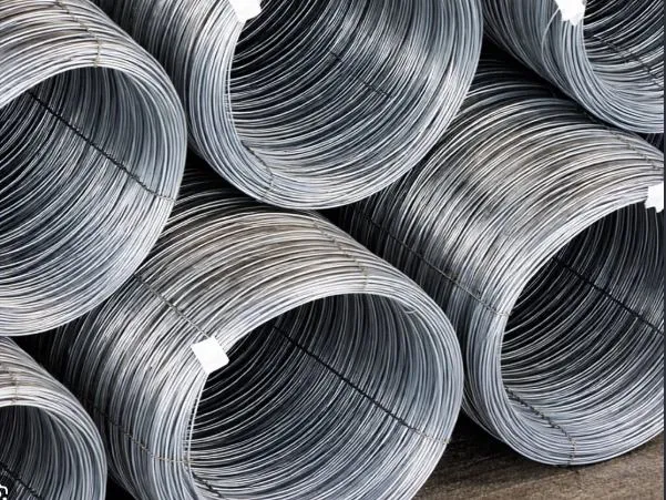
High-quality ERNiFeCr-2 TIG welding wire is available in different diameters for precision TIG welding applications.
Need ERNiFeCr-2 filler wire for your Inconel 718 welding project? Contact us for product specifications, available diameters, certifications, and a competitive quotation.
📧 Email: support@ronsteel.com
📞 Whatsapp: +8617773160488
Successful TIG welding of Inconel 718 requires careful control from joint preparation through post-weld treatment.
Before welding:
During welding:
After welding:
With proper control of welding parameters, filler metal, shielding, heat input, and post-weld treatment, TIG welding can produce reliable Inconel 718 joints for demanding aerospace, energy, nuclear, and marine applications.
Ronsco is a trusted global supplier of nickel alloy and stainless steel welding wires, including Inconel, Hastelloy, and Monel series. Our products are manufactured to meet industry standards and are widely used in demanding applications such as aerospace, oil & gas, chemical processing, and power generation. Explore our resource center for the latest industry insights, product knowledge, and technical references.
Contact us for a quote or technical assistance.


 English
 Español
 русский язык
 اللغة العربية